Caupayan, Jedda Anne G. BSEd-4
Logic Gate
I.
Definition
In
a digital circuit, logic gates can be found and those serve as digital systems’
elementary building block. Most of the
logic gates have one output and two inputs. The logic gates are AND, OR, NOT,
NAND, NOR, EXOR and EXNOR gates. At any given
moment, every terminal is in one of the two binary conditions low (0) or high
(1), represented by different voltage levels.
II.
Types
1.
AND Gate


The AND gate is
an electronic circuit that gives a high output (1) only if all its inputs are
high. A dot (.) is used to show the AND
operation i.e. A.B. Bear in mind that
this dot is sometimes omitted i.e. AB
2. OR Gate


The OR gate is
an electronic circuit that gives a high output (1) if one or more of its inputs
are high. A plus (+) is used to show the
OR operation.
3. NOT
gate


The NOT gate is
an electronic circuit that produces an inverted version of the input at its
output. It is also known as an
inverter. If the input variable is A,
the inverted output is known as NOT A.
This is also shown as A', or A with a bar over the top, as shown at the
outputs.The diagrams below show two ways that the NAND logic gate can be
configured to produce a NOT gate. It can also be done using NOR logic gates in
the same way.
4.
NAND Gate


This is a
NOT-AND gate which is equal to an AND gate followed by a NOT gate. The outputs of all NAND gates are high if any
of the inputs are low. The symbol is an AND gate with a small circle on the
output. The small circle represents inversion.
5.
NOR Gate


This is a
NOT-OR gate which is equal to an OR gate followed by a NOT gate. The outputs of all NOR gates are low if any
of the inputs are high. The symbol is an OR gate with a small circle on the
output. The small circle represents inversion.
6.
EXOR Gate


The
'Exclusive-OR' gate is a circuit which will give a high output if either, but
not both, of its two inputs are high. An
encircled plus sign () is used to show the EOR operation.
7.
EXNOR Gate


The
'Exclusive-NOR' gate circuit does the opposite to the EOR gate. It will give a
low output if either, but not both, of its two inputs are high. The symbol is
an EXOR gate with a small circle on the output. The small circle represents
inversion.
III.
Logic Gate Symbols

IV.
Applications
1.
Burglar
alarm
When the switch is closed one input of the NAND gate is
LOW. When the LDR is in the light the other input is LOW. This means that if
either of these things happen, i.e. the switch is closed or the light is on one
of the inputs is LOW, the output is HIGH and the buzzer sounds..

Retrieved from: http://goo.gl/UTXrcV
2.
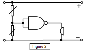
Freezer
warning buzzer
When the thermistor is COLD its resistance is
LARGE and the input to the NAND gate is high.
Since the NAND gate is connected as an INVERTER the output is LOW.
As the thermistor warms up its resistance decreases, the voltage across it
falls and the input to the NAND gate falls.
When it becomes low enough the output becomes HIGH and the buzzer sounds.
Retrieved from: http://goo.gl/UTXrcV
Retrieved from:


